ⅠMain technical specifications:
1. Maximum deadline load:410kN
2. Sensor:JZ500A.1.6
3. Output pressure of deadline anchor (Sensor):6.83MPa.
4. Error of output pressure of deadline anchor (sensor) :±1.0%FS.
5. Wire line size:Φ38mm, 35mm
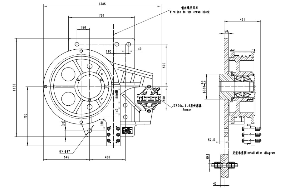
6. Overall dimension: 1385mm×1270mm×490mm
7. Weight: 1200kg
8. The deadline anchor is wall mounted onto the connection board on the
inner side of the derrick.
9. Environmental temperature: -40~50℃
Ⅱstructure and installation:
2.1 Structure:
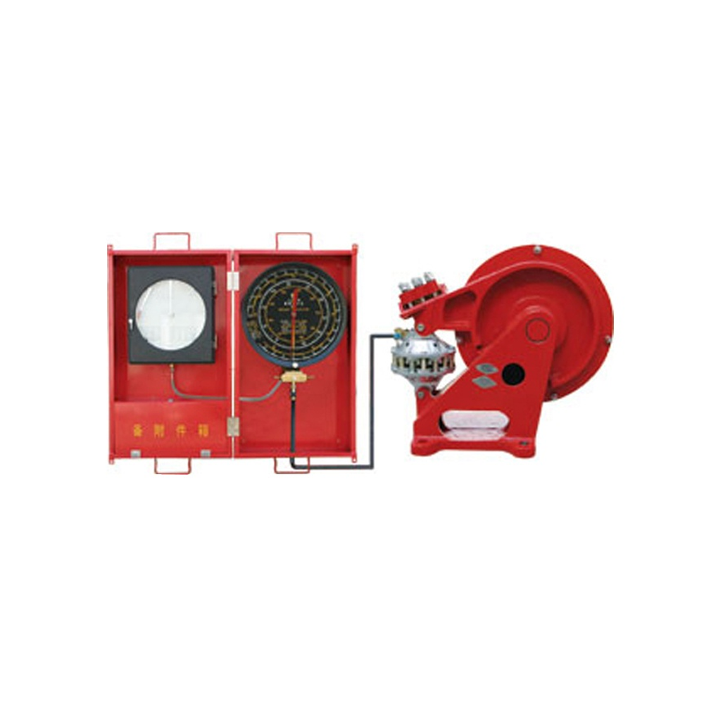
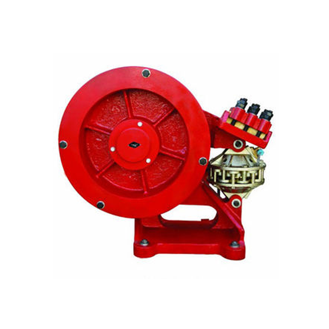
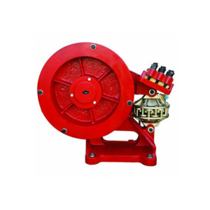
JZG41E Deadline Anchor consists of a drum, a base and a load sensor, as
shown in Figure 1.
Load sensor is one of the main parts of deadline anchor, and it converts
deadline load into hydraulic signal by compressing the liquid in the sensor via
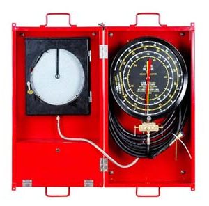
the diaphragm. The hydraulic signal is then transmitted to weight indicator and
recorder. On the sensor, a quick female connector, a self-sealing male
connector and a preserved plug are installed.
2.2 Installation, operation and maintenance
1) Put the gibbous parts on the base of deadline anchor into the holes in the
inner side of connection board on the derrick, and then fasten the deadline
anchor tightly on the connection board with bolts, nuts and washers.
2) Wrap the deadline round the drum three turns along the grooves of the drum,
then thread the deadline through the clamp, fasten it with bolts, nuts and press
block. Attention: The deadline clamp and deadline must be put properly and
tightly, in case slide of deadline. The wire line shall not touch any other thing on
the derrick.
3) Connect a hand pump with the oil injection connector of sensor. Operate the
hand pump to remove gas from and inject oil into the sensor. Pump hydraulic
fluid into the sensor until the weight indicator indicates 20~30% full scale.
Exhaust air at bleed plug. If there is air inside the sensor, the oil spouts from
the sensor is uncontinuous and sounds puff-puff; if there no gas in, the oil
spouts from the sensor is continuous with no puff-puff sound. Repeat the
operation at least three times and make sure all the air in the sensor is
exhausted and the sensor is fully filled. Please do not pump the sensor without
oil in the hand pump or air will be pumped into the hydraulic system,
4) During oil injection and daily drilling process, check regularly if there is
sufficient oil in the sensor (observe the gap between the upper press plate and
the lower plate of rubber diaphragm inside the sensor and see if it is in
accordance with the condition when the sensor if fully filled.). Re-fill oil into the
sensor if necessary.
5) Seat the travelling block system onto the drill platform while injecting oil or
refilling oil into the sensor and make sure there is no load on the deadline
anchor sensor (weight indicator) (this is very important). Remove all the air and
surplus liquid and have weight indicator pointer point to zero. Repeat the
oil-injection and gas-removal operation at least three times till all the air in the
hydraulic system is completely eliminated. This is one of the most important
measures to be taken to ensure correct reading of the instrument.
6) Every day, before operation, clear debris, mud, and ice on the sensor, and
check the gap between the upper and lower press plates. Check and see if there is leakage at the connection place. Solve any possible problems in time.
7) Regularly (usually 12months) apply some lubricant from the oil injection port
in the drum end cap with a grease gun to lubricate the bearing so that it can
rotate freely. Lubricating grease shall be Great Wall 7023B low-temperature
type.
8) Please use 45# transformer oil (M / D TOTCO W15-4 low-temperature fluid
for the hydraulic system is recommended if the instrument is to be use din the
environment with temperature below -40℃). The hydraulic oil used by the
instrument should be clean and precipitation-free to prevent hose and
connector from being clogged and ensure the reliable performance of the
instrument.
ⅢAttentions:
1. JZG41E Deadline Anchor must be used with JZ500A.1.6 sensor of 6.83MPa
and corresponding secondary instrument (weight indicator and recorder). Even
for the same type of drilling rig, the wire line it uses may be different, please
indicate in your order the size of wire line so that we can equipped the deadline
with corresponding clamp.
2. According to the maximum deadline load, determine the type of drilling rig it
can be used on.
3. Select a correct secondary instrument (weight indicator and recorder)
against the number of lines of traveling block and the maximum deadline load.
4. Bolts, relevant nuts and washers that are used to install JZG41E Deadline
Anchor should be equivalent to or above Grade 8.8. Tightening torque on M42
bolt (or stud) shall be: 1200±30n.m.
5. The design of installation board for deadline anchor should comply with
Attached Figure 2. The detailed installation place should be determined by the
rig manufacturer.
Ⅳ Spare Part list
| No | Part No | Name | Unit | Quantity | Remarks |
|---|---|---|---|---|---|
| 1 | JY246.4B | Long connection hose | Piece | 1 | 20m |
| 2 | SZT5A | Hand pump | Set | 1 | With a piece of 5-meter hose |
| 3 | JY248-10 | Diaphragm | Pjece | 2 | |
| 4 | JY250.2.1 | Self-sealing female connector | Pjece | 2 | |
| 5 | JY248.2 | Self-sealing male connector | Pjece | 2 | |
| 6 | JY246.4.1 | Quick male connector | Piece | 2 | |
| 7 | JY248.6 | Quick female connector | Piece | 2 | |
| 8 | 45#transformer oil | Bottle | 2 | 2kg/bottle | |
| 9 | M/D W15-4 hydraulic oi | Bottle | 1 | 3.8L/bottle | |
| 10 | JZG42A-3 | Clamp | Set | 1 | φ38mm,or 35mm |
Ⅴ. DECLARATION:
1.THE DEADLINE ANCHOR IS FORBIDDEN TO BE USED OVERLOAD.
PARTS OF DIFFERENT TYPES MUST NOT BE MATCHED TOGETHER.
AND WE WILL NOT BE LIABLE FOR ANY INSTRUMENT DAMAGE, HUMAN HURTS, AND OTHER ACCIDENTS CAUSED BY IMPROPER USE!
2. WE WILL ALSO NOT BE RESPONSIBLE FOR THE QUALITY,
TECHNICAL SPECIFICATIONS, TECHNICAL INTERFACE AND OTHER
ASPECTS OF THE SECONDARY INSTRUMENT AND ITS SPARE PARTS
THAT ARE NOT MANUFACTURED BY OUR COMPNAY!
Ⅵ ATTACHMENT:
1. STRUCTURAL DIAGRAM AND DETAILED PART LIST
2. INSTALLATION,OUTLINE DRAWING
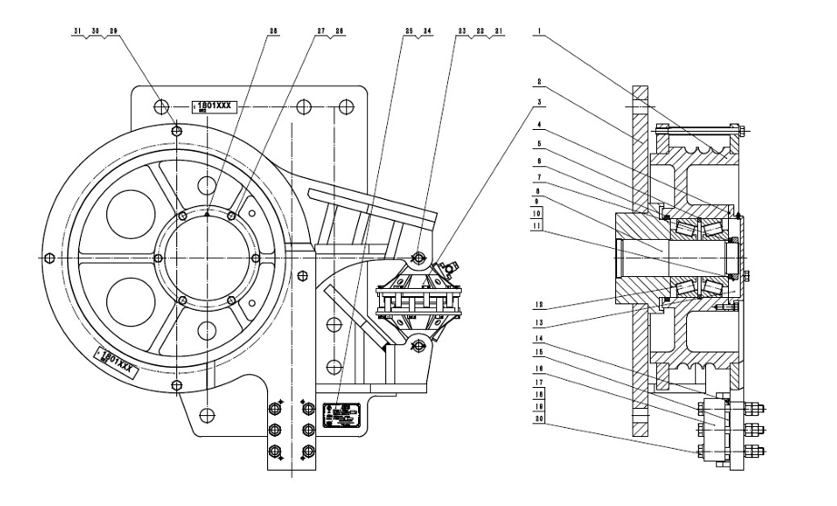
| No | Part No. | Name | Qty | No | Part No. | Name | Qty |
|---|---|---|---|---|---|---|---|
| 1 | JZG41E.1 | Drum | 1 | 17 | GB/T 97.1-2002 | Flat washer,Grade A,24 200HV | 6 |
| 2 | JZG41E.2 | Base | 1 | 18 | GB/T 5782-2000 | Hexagonal head bolt, M24x200-8.8 polish rod≤110 | 6 |
| 3 | JZ500A.1.6 | Sensor | 1 | 19 | GB/T 93-1987 | Standard spring washer 24 | 6 |
| 4 | φ4 rubber tape | 1 | 20 | GB/T6170-2000 | Type 1 Hex nut M24 -8 | 12 | |
| 5 | JZ500.1-5 | Expansion ring | 1 | 21 | JZ500A.1-3 | Shaft pin | 2 |
| 6 | JZ500.1-6 | Oil seal | 1 | 22 | GB/T 848-2002 | Small washer Grade A 24 140HV | 2 |
| 7 | JZG41E-3 | End cap | 1 | 23 | GB/T 91-2000 | Cotter pin 5×40 | 2 |
| 8 | JZ500A.1-4 | Shaft | 1 | 24 | J∠G-MP-API8G-1 | Deadline anchor monogram nameplate | 1 |
| 9 | GB/T 886-1986 | Shaft shoulder retainer ring 110×135 | 1 | 25 | GB/T 827-1986 | Nameplate rivet 3×10 | 4 |
| 10 | GB/T 858-1988 | Check washer for round nut 105 | 1 | 26 | GB/T 93-1987 | Standard spring washer 16 | 6 |
| 11 | GB/T 812-1988 | Round nut M105x2 | 1 | 27 | GB/T 5783-2000 | Hex. Head bolt, fully threaded,M16x40-8.8 | 6 |
| 12 | GB/T 297-1994 | Tapered roller bearing 32324 | 2 | 28 | JB/T 7940.1-1995 | Straight-through oil forced cup M10x1 | 1 |
| 13 | Low-temperature lubricatinggrease | 2kg | 29 | GB/T 93-1987 | Standard spring washer 20 | 4 | |
| 14 | GB/T 119.1-2000 | Cylindrical pin 10u8x50-A3 | 4 | 30 | GB/T 5782-2000 | Hexagonal head bolt M20x280 -8.8 | 4 |
| 15 | JZG42A-3 | Clamp | 1 | 31 | JZG42A-4 | Sleeve | 4 |
| 16 | JZ500.1-7 | Press block | 1 | 32 |

Reviews
There are no reviews yet.