
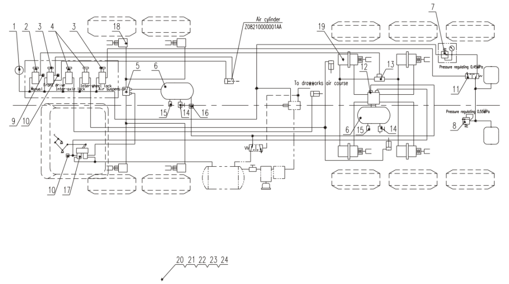
Schematic diagram of chassis air system (Drawing NO.:Z08270000003AA)
| S/N. | Drawing No. | Description | Qty |
|---|---|---|---|
| 1 | 3800200005 | Pressure gouge | 1 |
| 2 | 5000100085 | Manual broke valve | 1 |
| 3 | 4900300052 | Emergency broke valve | 2 |
| 4 | 4900300051 | 2 position 3 way button valve | 2 |
| 5 | 5000100084 | Brake accelerotion volve | 1 |
| 6 | Z08250000002AA | Air cylinder | 2 |
| 7 | 4900300037 | Pressure reducing valve | 1 |
| 8 | 5002400087 | Overflow yalve | 1 |
| 9 | 5001900177 | Pressure olarm switch | 1 |
| 10 | 5000100063 | Switch of brake light | 2 |
| 11 | 3801950004 | 2 position 3 way valve(normal open) | 1 |
| 12 | 4900300030 | Emergency relay valve | 1 |
| 13 | 4900300029 | Quick releose valve | 1 |
| 14 | 4900300057 | Woter draining valve | 2 |
| 15 | 4900300056 | Copper safety valve | 2 |
| 16 | 4900300012 | Check valve | 2 |
| 17 | 5000100086 | Double chamber brake volve | 1 |
| 18 | 5000200003 | Front oxle brake chamber | 4 |
| 19 | 5000200004 | Rear axle brake chamber | 4 |
| 20 | Z08110000001AA | Corrier brake lines | 1 |
| 21 | Z08120000001AA | Differential lock lines | 1 |
| 22 | Z08130000001AA | Air suspension lines | 1 |
| 23 | Z08140000001AA | Front drive shutter lines | 1 |
| 24 | Z08260000001AA | Air control box of cab | 1 |
Reviews
There are no reviews yet.